
Beam Rebar Drawings

Beam Rebar Drawings

Complete beam reinforcement layouts including stirrups, anchorage, and lap splice locations.

Beams Rebar Shop Drawings & Detailing

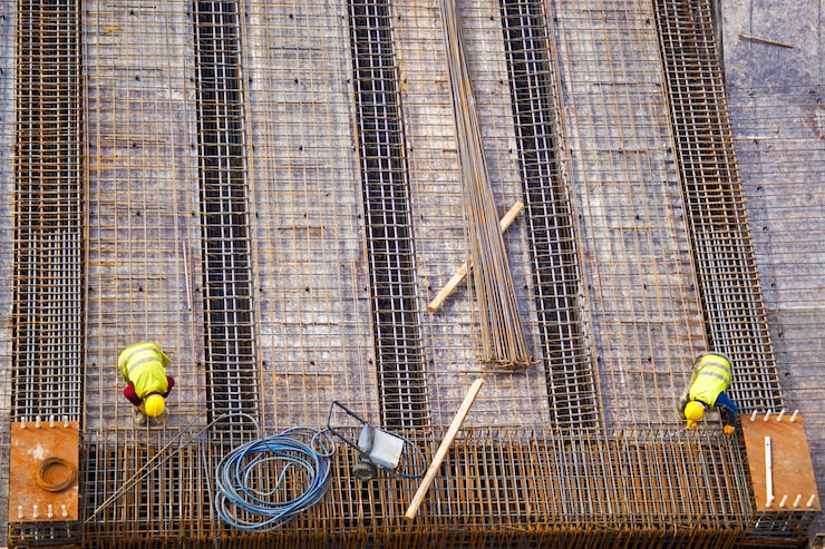
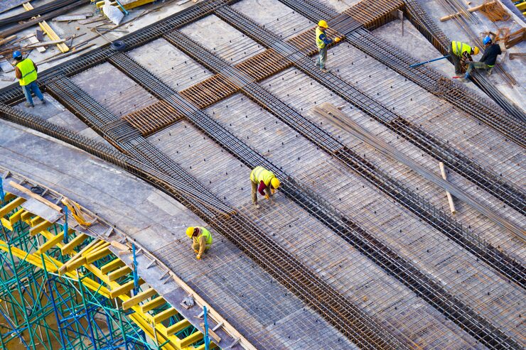
Beam rebar shop drawings define the complete reinforcement layout, including top (negative) and bottom (positive) longitudinal bars, shear reinforcement (stirrups/links), anchorage lengths, and lap splice locations in accordance with design requirements. Steel placement is clearly indicated with precise spacing, bar sizes, cover requirements, and support conditions to ensure proper load transfer and structural performance. Each reinforcement element is assigned a unique bar mark linked to the bar bending schedule for accurate fabrication and traceability. Beams are identified using a consistent naming and nomenclature system (e.g., B1, B2, TB1 for tie beams, SB for secondary beams), aligned with structural drawings and grid references.

More Services

Structural Rebar Detailing

Accurate reinforcement layouts for all structural elements, compliant with international codes.

CAD Drafting

Clean, organized CAD files delivered in DWG and PDF — ready for immediate use.
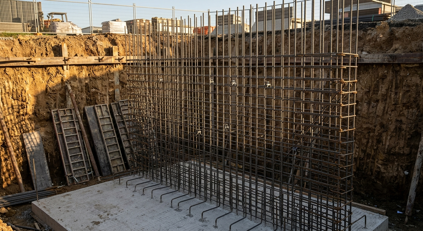
Retaining Wall Drawings

Reinforcement systems engineered for lateral pressure, crack control, and constructability.
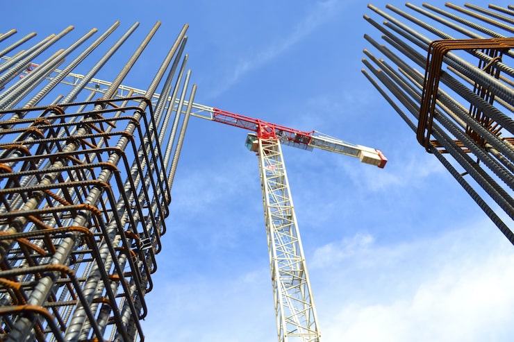
Column Rebar Drawings

Full column reinforcement with ties, splice zones, and confinement details.
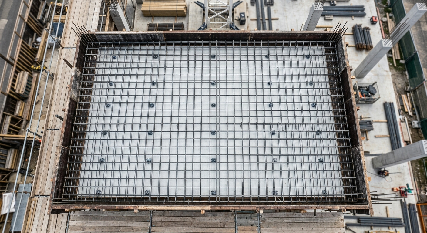
Slab Rebar Drawings

Main and distribution steel layouts for flat, one-way, and two-way slab systems.

Let's Start Your Project with Precise Rebar Detailing

From bending schedules to fully coordinated shop drawings, our team is ready to deliver accurate, code-compliant detailing tailored to your project.